
Rung 9 · See fields and systems
Find series resonance
Sweep an RLC circuit around 50 Hz and watch current peak when energy exchange lines up.
Knowledge this exercise builds on
Practice loop
Try each step before revealing its answer.
The task stays visible. Revealing a numbered answer remembers that stage as explored in this browser. It is not a grade.
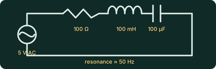
- One adjustable 5 V peak AC voltage source
- One 100 Ω resistor
- One 100 mH inductor
- One 100 µF capacitor
- Voltage and current scopes
Estimate the resonant frequency with:
f₀ = 1 / (2π√LC)Predict how current at 20 Hz and 100 Hz will compare with current near 50 Hz.
Reveal predictionHide prediction
For 100 mH and 100 µF:
f₀ ≈ 50.3 HzCurrent should be highest near 50 Hz and lower at 20 Hz and 100 Hz. Below resonance, current leads source voltage. Above resonance, current lags it.
Place the resistor, inductor, and capacitor in one series loop. Start the source at 20 Hz, then test 50 Hz and 100 Hz.
Show build checkHide build check
Use one unbranched path:
AC source -> 100 Ω -> 100 mH -> 100 µF -> source returnKeep component values fixed and change only source frequency. Scope source voltage and loop current.
Measure current amplitude and its timing relative to source voltage at 20 Hz, 50 Hz, and 100 Hz.
Reveal expected resultHide expected result
Current reaches its maximum near 50 Hz, where the inductor and capacitor reactances nearly cancel. At 20 Hz the circuit is net capacitive, so current leads source voltage. At 100 Hz it is net inductive, so current lags. Resistance limits the resonance peak.
Explain how the capacitor’s electric field and inductor’s magnetic field exchange energy, and how the resistor damps that exchange.
Reveal explanationHide explanation
Near resonance, energy moves back and forth between the capacitor’s electric field and the inductor’s magnetic field. The resistor converts some of that energy to heat every cycle, which damps the exchange. Resonance is frequency-selective behavior, not free energy. The source replaces the energy dissipated by resistance.
Optional referenceReveal reference circuitCompare only after you build. Opening this panel does not contact Falstad.
The reference is editable and uses the same export text as the external link. Loading it contacts falstad.com. The written exercise and schematic remain useful if Falstad is unavailable.
Safety boundary
This is a low-voltage educational model.
Do not translate it into mains construction, household wiring, battery-pack work, or real protection settings. Real electrical systems need rated components, proper protection, test equipment, and qualified safety judgment.