
Rung 10 · See fields and systems
Move power with less line loss
Compare direct and transformed transmission at the same delivered load power.
Knowledge this exercise builds on
Practice loop
Try each step before revealing its answer.
The task stays visible. Revealing a numbered answer remembers that stage as explored in this browser. It is not a grade.
- One 10 V peak, 50 Hz AC source for the transformer path
- One adjustable 50 Hz AC source for the direct path
- One 1:10 step-up transformer
- Two 5 Ω line resistors in each path
- One 10:1 step-down transformer
- One 10 Ω load resistor in each path
- Power and current scopes
Predict which arrangement carries more line current when both loads receive about 4.9 W:
- A direct source adjusted to about 19.8 V peak to overcome the line drop.
- Voltage stepped up before the line and stepped down near the load.
Use P = VI and P_loss = I²R to explain the prediction.
Reveal predictionHide prediction
The direct path carries more line current. At matched load power, stepping voltage up by 10 reduces ideal line current by about 10. Because resistive loss depends on current squared, the stepped path should lose about 100 times less power in the line.
Build both paths with 10 V peak sources first. Observe that this is not a same-power comparison: the direct path delivers about 1.25 W to its load, while the ideal transformer path delivers about 4.9 W.
Then raise only the direct source to about 19.8 V peak. This makes its load power approximately match the transformer path, so line current and heating can be compared fairly.
Show build checkHide build check
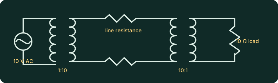
Build two separate paths with identical 10 Ω loads and 10 Ω total line resistance. The transformer path should be:
10 V peak source -> 1:10 step-up -> line resistance -> 10:1 step-down -> 10 Ω loadKeep both transformer ratios and loads fixed. Adjust only the direct source to about 19.8 V peak for the matched-power comparison.
Record load power, line current, and total line-resistor loss for both paths after matching load power.
Reveal expected resultHide expected result
Both loads receive about 4.9 W. The expected comparison is:
direct line current      -> about 0.70 A RMS
direct line loss         -> about 4.9 W
stepped-up line current  -> about 0.070 A RMS
stepped-up line loss     -> about 0.049 W
Real transformers and lines have additional losses. This exercise isolates the current-squared relationship.
Explain why the direct source had to be raised to match delivered power, why stepping voltage up lowers line current, and why the voltage must be stepped down again near the load.
Reveal explanationHide explanation
Transformers trade voltage and current. At the same delivered load power, 10 times less line current produces about 100 times less resistive line loss in this idealized comparison.
The direct source must be raised because its larger line current creates a larger voltage drop before the load. The transformer path carries the same power at higher line voltage and lower line current, then steps voltage back down so the load receives the intended level.
Optional referenceReveal reference circuitCompare only after you build. Opening this panel does not contact Falstad.
The reference is editable and uses the same export text as the external link. Loading it contacts falstad.com. The written exercise and schematic remain useful if Falstad is unavailable.
Safety boundary
This is a low-voltage educational model.
Do not translate it into mains construction, household wiring, battery-pack work, or real protection settings. Real electrical systems need rated components, proper protection, test equipment, and qualified safety judgment.