
Rung 7 · See change over time
Rectify and smooth AC
Build a bridge rectifier, then use a capacitor to reduce the valleys in its output.
Knowledge this exercise builds on
Practice loop
Try each step before revealing its answer.
The task stays visible. Revealing a numbered answer remembers that stage as explored in this browser. It is not a grade.
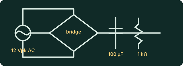
- One 12 V peak, 50 Hz AC voltage source
- Four diodes
- One 1 kΩ load resistor
- One 100 µF capacitor
- Input and output scopes
Predict how a bridge uses both AC half-cycles. Then predict what the capacitor does near each waveform peak and valley.
Reveal predictionHide prediction
The bridge redirects both AC half-cycles so load current keeps one direction. A 50 Hz source therefore produces 100 Hz rectified pulses. The capacitor charges near each peak and supplies part of the load as the rectified voltage falls between peaks.
Build the bridge first without the capacitor. Confirm full-wave pulsing output, then place the capacitor in parallel with the load.
Show build checkHide build check
Orient the four diodes so either source polarity drives current through the load in the same direction. Connect the 100 µF capacitor directly across the load, with its positive side on the bridge’s positive output.
Measure output frequency without the capacitor. Then compare output ripple with 47 µF, 100 µF, and 470 µF. Lower the load resistance and record what changes.
Reveal expected resultHide expected result
The unsmoothed bridge output pulses at 100 Hz. Increasing capacitance from 47 µF to 470 µF reduces the fall between peaks, so ripple becomes smaller. Lowering load resistance draws more current and discharges the capacitor faster, so ripple increases.
Explain why the capacitor charges near peaks, supplies part of the load between peaks, and cannot produce perfectly flat DC by itself.
Reveal explanationHide explanation
Rectification controls direction. Smoothing shifts stored energy through the short gaps between rectified peaks. Regulation would be a later stage.
The capacitor charges only when bridge voltage rises above capacitor voltage. Between peaks, it releases stored electric-field energy into the load, so its voltage must fall somewhat. That repeating fall is ripple.
Optional referenceReveal reference circuitCompare only after you build. Opening this panel does not contact Falstad.
The reference is editable and uses the same export text as the external link. Loading it contacts falstad.com. The written exercise and schematic remain useful if Falstad is unavailable.
Safety boundary
This is a low-voltage educational model.
Do not translate it into mains construction, household wiring, battery-pack work, or real protection settings. Real electrical systems need rated components, proper protection, test equipment, and qualified safety judgment.